User s Manual. Depth of Cut Adjustment Depth of cut is controlled by raising or lowering the table: 1 Loosen lock knobs (A, Fig 9) 2 Raise or lower the table to the desired position 3 Tighten lock knobs before operating machine Maximum fullwidth depth of cut is 1/8" A limiter (A, Fig 10) is provided to restrict the depth of cut on full width planing from 3/16" to 1/8" -- --_ Fig10,~/---, 13 - '-""-' n_- ""' I ~ I! M-708538 Ph. 2012NB Description 304mm (12") Automatic Thickness Planer CONCEPTION AND MAIN APPLICATIONS * Compact and light weight (27 Kg./59 lbs) automatic thickness planer for easier, MODEL NO. 10 BANDSAW OPERATING INSTRUCTIONS MODEL: W715 Charnwood, Cedar Court, Walker Road, Bardon, Leicestershire, LE67 1TU Tel. MODEL W " PLANER PARTS LIST. 33 It t', J,!,-,,--~,--,_, Head Assembly 1 JWP15H-001 Head Casting """'''''''''''''''''''''''''''''''''''''' 1 2 TS Set Screw M1 Ox15-12 """""'"'''''' 8 3 PG-C01 Cutter Head """'''''''''''''''''''''''''''''''''''''' 1 4 TS """'"'' Set Screw M5x8-12 """'"'''''''''''''''''''' Knife (set) 3 6 JWP15H-006 Knife Bar 3 7 JWP15H-007 Hex Head Screw """'''''''''''''''''''''''''''''''''''' TS Washer M TS Nut " " M1OX125 "'"'''' 1 12 BB-6205ZZ Ball Bearing " """'''''''''''''''''''''''''''''''''''''' 1 13 JWP15H-013 Key, 8x7x35 ""'"'''''''' 1 14 JWP15H-014 Machine Pulley """'"'''' 1 15 JWP15H-015 Washer "'''''''''''''''' 2 17 JWP15H-017 Motor Pulley """"""""""'''''''''''''''''''''''' 1 18 JWP15H-018 Infeed Roller " """'''''''''''''''''''''''''''''''''''''' 1 19 JWP Bushing ""'''''''''''' 4 20 JWP 15H-020 Spring """""""'"'''''''''''''''''''''''' """""" """"'"'''' 4 21 JWP15H-021 Set Screw M22x15-20 ""'"'' 4 22 JWP15H-022 Plate """'''''''''''''''''''''''''''''''''''''' 4 23 TS Hex Head Screw M8x """""""'"'''''''' 6 24 TS ,Set Screw M6x "'''''''' 7 25 TS Nut M6x JWP15H-026 Key 5x5x22 '"'''''''''''''''''''''''''' 2 27 JWP15H-027 Sprocket """""""'''''''''''''''''''''''''''''' 1 28 JWP15H-028 Washer 1/4 """'"'''''''''''''''''''''''''''''' 2 29 TS Hex Head Screw M6x10-16 """"'"'''''''''''''''' 2 30 JWP15H-030 Outfeed Roller 1 31 JWP15H-031 Sprocket "'"'''''''''''''''''''''''''''''''''''''''''' 1 32 JWP15H-032 Locking Bolt """""'''''''''''''''''''''''''''''''' 1 33 JWP15H-033 Retaining Ring STVV-12 "'"'''''''''''''''''''''''''' 1 34 JWP15H-034 Chipbreaker '"'''''''''''''''''''''''''''''''''' 1 35 TS Nut M12x1 75 """""'''''''''''''', 1 36 JWP15H-036 Plate Spring 3 38 TS " Hex Head Screw M6X JWP15H-039 '''''''''''''''' Shaft ""'"'''''''''' 1 40 JWP15H-040 Deflector Plate '''''''''''''''''''''''''''''''''''''''''''' 1 41 JWP15H-041 Anti-Kick Finger JWP15H-042 Collar '"'''''''''''''''' """"'" JWP15 H-043 Shaft " 1 44 TS Set Screw M8x """""""""""'" 1 45 JWP15H-045 Retaining Ring ETVV JWP 15H-046 Limiter Plate "''' " '"'''''''''''''''''''''''''''''''''' ""'" 1 47 TS FlatHeadScrew M5xO8-12 "'"'''''''''''''''''''''' 2 48 JWP15H-048 Upper Cover "'" " 1 50 JWP 15H-0500 " Collector Hood 1 51 JWP15H:051 Roller Stand '''''''''''''''''''''''''''''''''''''''''' '''''''''''''''''''''''''''''''''''''''''''' 3 52 JWP 15H-052 Roller 2 53 TS c Hex Socket Cap Screw M6x JWP15H-054 ~orm Gear Box ~ ''''''''''''''''''''''''''''''''''''',,,,,,, 1 55 JWP15H-055 Worm """'''''''''''''''''''''''''''''''''''''''''''''' '''''''''''''''''''''''''''''''''''''''''''' 1 56,,,~,,,,,,,,,B OZ ",~"~,,,,~,,,,, Ball,,Be a ri n q"'~"'""n','n'''''''~''''''''',=~,,""",,"~~,~,~,~,-",-"o""~"~,,-,~,,,,,,~'=,">,~o,,,'-~--, 35 {J ::: ~ 57 JWP15H-057 Retaining Ring, RTW-30, 1 58 JWP15H-058 Key 4x4x JWP15H-059 Hand Wheel 1 60 JWP15H-060 '"'''''''''''''''''' Handle "'" 1 61 JWP15H-061 ijj: Cover '''''''''''''''''''''''''''''''''''''''''''''''''''' 1 62 JWP15H-062 Spring pin, 2 63 PF-C22 """""'''''''''''''''''' Plate " 2 64 TS Hex Head Screw M6x TS Hex Socket Cap Screw M8x JWP15H-067 Bolt """"""'''' """"'" 2 67 TS " Washer, 5/16 """""" 2 68 TS NUt P"'''''''''''''''''''''' 5/ ~P-MA-=e26 Pulley Cover JW 4-:pI':7"CJf tj 1 70 JWP15H-072 Knob :, 2 71 JWP 15H-073 Chain " "'"'''''''''''' "'" 1 73 PG-C05 Label "'"'''''''''''''''''' 1 IfJ-0r:F 74 VB-M59 """"""""'"'''''''' V-BelL '1" P ' 2':""'~'O"'" M59 '"'''''''''''''' 3 75 ~n-:: Pulley Guard ::IU o3: '2'l"'''''' 1 76' TS Hex Socket Cap Screw M6x PF-C26, Washer 4 78 PA-C56 Stud '''''''''''' 1 79 PA-C57 Idle Pulley 1 80 PA-C58 Bracket 1 81 PA-C59 Stud """""""""""'"'''''''''''''''''''''''''''''' 1 82 PA-C60 Hanger, 1 83 PA-C61 Spring """"""'''''''''''''' 1 84 PA-C62, Washer " 1 85 JWP15H-076 "'''''''''''Q;biSwitch Bracket """"'"'''''' 1 86 JWP-t5t! 1 Specifications 2 Safety Rules.3-4 Unpacking.5, D R I L L - G R I N D E R S BL 13D-2 2 Table of contents 1. For questions or help with this product contact Tech Support at (570) or, Operating Instructions and Parts Manual 15-inch Thickness Planer Models JWP-15DX and JWP-15HH, Assembly Instructions and Parts Manual 5C Collet Closer for GHW Lathes Model CC-GHW, Assembly Instructions and Parts Manual 5C Collet Closer for ZX Series Lathes Model CC-ZX, ET-110 EXTREMA MACHINERY COMPANY, INC. P.O. Since 04/18) 66V A A A 28A, MODEL T27451/T " & 20" SPIRAL CUTTERHEAD INSTRUCTIONS, GENERAL OPERATIONAL PRECAUTIONS PRECAUTIONS ON USING CUT-OFF MACHINE, G0513X2 Main -87- G0513 Series Bandsaws 82V V2 82-6V2 95A V2 82-5V2 82-1V2 82-4V V A, Electric Router. Help to protect the environment, take the packaging to the local amenity tip and place into the appropriate, SECTION 9: PARTS Main Breakdown 2 115 75 113 112 8 9 7 8 11 4 5 3 3 85 81 79 78 90 84 68 69 69 68 87 86 86 91 95 98-2 98-1 98-3 98-4 98 98-8 98-9 98-5 98-6 99 97 98-7 100 92 114 108 107 110 109 111 104, PT10081 5 SPEED MINI DRILL PRESS INSTRUCTION MANUAL MODEL NO.ZJ4113 CAREFULLY READ THE INSTRUCTIONS BEFORE YOU USE THE DRILL PRESS. Model SFI-60. 2 Remove the stand cover on the rear of the stand -~--- 3 From the inside of the stand, loosen the nut (A, Fig 13) 4 Raise or lower the motor plate (B, Fig 13) by turning tbejjlil C~,s19J 31LlntilJhe correct tensionis achievedcorrecttensionhasbeenobtained when light finger pressure causes Fig 13, 15 """""~'-h approximately of the belts 1/4" deflection in the center span 5 Tighten the nut (A, Fig 13) to hold the adjustment 6 Replace the stand cover Knife Adjustment & WARNING Use extreme caution when placing handsch~~t' the cutting knives; they are very sharp andean cause severe cuts!,:;f7 Failure to comply may cause serious jnjuryr:~~:c CAUTION ~"Anyadjustment or replacement of knivesiffili~~7, V be done to all three knives at the same timef~}' Failure to comply may result in an out of balance cutterhead which may lead to bearing failurel e 1 Disconnect the machine from the power source Fig 14 2 Slightly loosen five bolts (A, Fig 14) 3 Carefully place knife setting gauge (B, Fig 14) on the cutterhead as shown in (Fig 14) When properly adjusted, the knife-edge should just contact the bottom of the center protrusion 4 To raise the knife, insert the hex wrench into the jacking screw (Fig 15) on either end of the cutterhead and turn counter-clockwise 5 To lower the knife, turn both jacking screws clockwise With a block of scrap wood (to protect fingers and the knife), push knife into cutterhead farther than it needs to be Final setting should always be made by raising the knife rather than lowering it / Knife Setting Guage \ Jacking Screw 6 Tighten all bolts (A, Fig 14) firmly 7 Repeat steps 2-6 for the other knives ~-- Fig 15, 17 Knife Removal and Installation 1 Disconnect the machine from the power source 2 To remove the knife,loosen five bolts (A, Fig 16) 3 Carefully removethe blade from the cutterhead by lifting straight out A piece of scrap wood wi/i aid removal 4 Insert the new knifeinto the cutterhead ~ \! PT10081 INSTRUCTION MANUAL 5 SPEED MINI DRILL PRESS CAREFULLY READ THE INSTRUCTIONS BEFORE YOU USE THE DRILL PRESS.
WARNING! (877) East (800) West. : 800-274-6848 Revision G1 03/2014 www.jettools.com, Assembly Instructions and Parts Manual 5C Collet Closer for ZX Series Lathes Model CC-ZX JET 427 New Sanford Road LaVergne, Tennessee 37086 Part No. Please dispose of packaging for the product in a responsible manner. Since 02/18) PARTS. Model W1745W (For Machines Mfd. Description Size Qty, SHAPER by INVICTA. Since 8/18) PARTS. Please read and fully understand the instructions in this manual before operation and keep this manual safe for future, TP1300 OWNERS MANUAL 13 INCH THICKNESS PLANER WITH LEGSET. The total procedure, MODEL H9291 12" BYRD SHELIX CUTTERHEAD INSTRUCTIONS The Model H9291 12" Byrd Shelix cutterhead is designed to replace the straight-knife cutterhead on the Grizzly jointer Model G0609. : 800-274-6848 Revision, MODEL G0453P POLAR BEAR SERIES 15" PLANER Manual Insert Congratulations on your purchase of a Model G0453P Planer! 25-200H. Page Model BR-3 (100 mm Blade) 115V/60Hz 4011003 220V/50Hz JPM-13CSX PLANER 708524XM 708524XT 230/50/1 400/50/3 PARTS LIST ERSATZTEILLISTE LISTE DE PIECES WMH Tool Group AG Bahnstrasse 24, CH 8603 Schwerzenbach www.wmhgrouptool.ch; info@wmhtoolgroup.ch Tel +41, W1669 & W1670 Parts 23 66V2 22 21 25 26 53A 62 63 89 64 9 65 24 20 15 16A 54 93 10 16A-1 81 77 94 53 79 102 103 28 36 8 30 19 31 32 32-1 109 28A 28 27 34 33 56 49 76 76 19-3 19-1 19-2 38-1 89 35 60 59, TECHNICAL INFORMATION Models No. Keep this manual safe for future reference. Ignoring this warning may lead to serious, 01550 10 x 6 Planer/Thicknesser Please read and fully understand the instructions in this manual before operation. Socket 2 Sub Stopper 3 O-Ring (S-16) 4 Locator (A) 5 Lock Sleeve (A) 6 O-Ring, Model G0490/G0490X (Mfd. W1669 & W1670 Parts PARTS. 12 SHEAR, PRESS BRAKE &SLIPROLL OPERATION MANUAL SPECIFICATION Cpacity: Roller : Die set sizes: Weight: 1mm thick (20gauge), 305 mm (12 ) width 38mm(1-1/2 ) 101.6mm(4 ), 76.2mm(3 ), 50.8mm (x2)[2 9x2]]. BOX 1349 Phone:253-351-6000 A WMH Company Auburn, WA 98071-1349 Fax: 1-800-274-6840 www.jettools.com, Operating Instructions and Parts Manual 15-inch Thickness Planer Models JWP-15DX and JWP-15HH JET 427 New Sanford Road LaVergne, Tennessee 37086 Part No. Register, SECTION 9: PARTS Headstock 120 121 113 115 112 111 110 109 108 105 106 107 135 101 119A 121 120 118 114 115 107 106 104 123 122 118 114 126A 105 126 103 102 126B 127A-1 131 127A 124 133 134 126C 129 130, To make this website work, we log user data and share it with processors. 20" hh planer 5hp 1ph helical head (2 pages), Jet tools owner manual woodworking planer jwp-16os (36 pages), Jet tools operating instructions planer jwp-208 (36 pages), 13-inch portable thickness planer (28 pages), Manual will be automatically added to "My Manuals", Inspect Work Table Parallel to Cutterhead, Adjusting Work Table Parallel to Cutterhead (Fine Adjustment), Adjusting Work Table Parallel to Cutterhead (Major Adjustment), Know the Transmitting Rollers of Your Planer, Height of Infeed Roller, Chipbreaker and Outfeed Roller, Troubleshooting: Mechanical and Electrical Problems, Planer Jet JWP-208 Operating Instructions And Parts Manual, Planer Jet JWP-13BT Operating Instructions And Parts Manual, Planer Jet JWP-15B Operating Instructions And Parts Manual, Planer JET JWP-201 Operating Instructions Manual, Planer Jet JWP-208HH Operating Instructions And Parts Manual, Planer Jet JPT-260 Operating Instructions Manual, Planer Jet JPM-13CS Operating Instructions And Parts Manual, Planer Jet JJP-10BTOS Operating Instructions And Parts Manual, Page 13: Inspect Work Table Parallel To Cutterhead, Page 14: Adjusting Work Table Parallel To Cutterhead (Major Adjustment), Page 15: Infeed And Outfeed Roller Spring Tension, Page 20: Troubleshooting: Performance Problems, Page 21: Troubleshooting: Mechanical And Electrical Problems, Page 33: Parts List: Stand And Motor Assembly. Parts List Index No. 1 Anti-Kickback Fingers Anti-kickback fingers (A, Fig 11) are provided to prevent the occurrence of kickback These fingers operate by gravity and must be inspected before each day's use for pitch or gum buildup The fingers must operate freely and move independently for correct operation t" Feed Rate Adjustment The JWP-15CS is equipped with selectable feed speed rollers that feed stock at 16 and 20 feet per minute Always change speeds while the planer is runnmg To adjust speed: 1 Push speed control lever (A, Fig 12) in fully for 20 feet per minute 2 Pull speed control lever half way out to disengage feed rollers Fig 11, 3 Pull out speed control lever fully for 16 feet per minute A j I 1 I I Adjusting Belt Tension 1 Disconnect the machine from the power source Fig 12 I I! TS-1541031Lock NutM8 4 2 JJP12-002Washer 4 3 JJP12-003Outfeed Table Bracket Shaft 1 4 JJP12-004Outfeed Table Bracket, SECTION 9: PARTS G7945/G7946 Main Parts 22 53 25 26 31 139 32 32-1 60 38 59 38-1 119 35 37 31 38-3 124 125 45A-2 45A-4 45A-1 31 60 45A-3V2 120 121 62 28 28-1 28 27 34 50 51 39 41 126 137 36 46 40 63 33, OPERATORS MANUAL SHAPER by INVICTA Model TI-14 INCLUDES VERSIONS: TI-14 V.02 NON-TILTING TI-14 V.03 TILTING SPINDLE TI-14 V.04 SLIDING TABLE TI-14 V.05 TILTING SPINDLE / SLIDING TABLE INVICTA USA English, Date Serial Number GROUND. Call (800) 523-4777 or visit www.grizzly.com/, 241-9895 18 GAUGE ELECTRIC METAL SHEAR Operator s Manual SAVE THIS MANUAL You will need this manual for safety instructions, operating procedures and warranty.
Having the Model Number and Serial Number of, MODEL W1.0X305A(12 ) MODEL W1.0X610A(24 ) HAND BENDING BRAKE ASSEMBLY&OPERATING INSTRUCTION 1 SAVE THIS MANUAL You will need the manual for the safety warning and precautions, assembly instructions, operating, SECTION 9: PARTS Table 26 27 25 24 23 28 33 31 22 30 21 29 34 32 20 35 19 36 18 15 16 17 37 35 36 39 30 13 8 14 11 12 38 10 40 34 29 9 54 53 56 52 41 51 42 50 43 49 17 3 46 48 44 2 7 4 6 5 46 45 47 4 1, 3889560 REEL ALIGNMENT GAGE OPERATING INSTRUCTIONS AND PARTS LISTS WARNING You must thoroughly read and understand this manual before operating the equipment, paying particular attention to the Warning, G0513X2 Main 55 17 48 7 16 55A 14 15 49 13 47 50 12 10 71 70 72 73 59 69 74 46 11 9 8 76 5 75 4 68 81 80 67 66 48 50 39 78 79 23 17-3 17-2 17-1 17-4 17-2 21 22 24 17-5 32 33 34 35 28 2 45 3 38 44 39 43, SECTION 9: PARTS Table 33 We do our best to stock replacement parts when possible, but we cannot guarantee that all parts shown are available for purchase. Quick Set Dovetail Jig FOR HELP OR ADVISE ON THIS PRODUCT PLEASE CALL OUR CUSTOMER SERVICE HELP LINE : 01509 500359 THE MANUFACTURER RESERVES THE RIGHT TO ALTER THE DESIGN OR SPECIFICATION TO THIS PRODUCT, TB & SB Series Drill Presses OWNERS MANUAL BENCH AND FLOOR DRILL PRESS TB-16 Series & SB-16-25-32-Series FOR YOUR OWN SAFETY AND OPTIMUM OPERATION READ INSTRUCTION MANUAL BEFORE OPERATING DRILL PRESS RETAIN, SECTION 9: PARTS Tables, Fence & Cutterhead 28 29 26 27 25 23 23 22 24 22 35 37 36 38 16 15 17 18 39 11 14 19 20 21 13 12 6 7 8 9 10 1 2 5 49 3 4 3 31 30 6 7 94 93 95 40 96 43 42 44 45 46 47 48 55 55-4, SECTION 9: PARTS Please Note: We do our best to stock replacement parts whenever possible, but we cannot guarantee that all parts shown here are available for purchase. Model DI-42. Industrivej 3-9 DK-9460 Brovst Tlf. ", INSTRUCTION BOOKLET AND WARRANTY INFORMATION 6 BENCH GRINDER. Read and understand the entire instruction manual before attempting set-up or operation of this machine! ;:: All adjustmwnts must be made with thel11a~l1ide disconnected from the power sc)urc:~r~-~r' Failure to comply may result in serious injury! : 800-274-6848 Revision D 08/2014 www.jettools.com, Assembly Instructions and Parts Manual 5C Collet Closer for GHW Lathes Model CC-GHW JET 427 New Sanford Road LaVergne, Tennessee 37086 Part No. WARRANTY This product is warranted against defects in materials and, Model W1745W (For Machines Mfd. PARTS. All safety and warning instructions, OWNER S MANUAL JWS-25CS HD Wood Shaper JET EQUIPMENT & TOOLS, INC. P.O. Open circuit in motor or loose connection. WARNING: NO PORTION OF THIS MANUAL MAY BE REPRODUCED IN ANY SHAPE OR FORM WITHOUT THE WRITTEN APPROVAL OF GRIZZLY INDUSTRIAL, ST1014 PARTS ST1014 Headstock Breakdown 112 114 23 104 105 108 102 106 20 19 21 22 101 100 103 111 38 14 15 37 46 44 47 45 107 93 39 41 40 67 110 109 74 75 76 11 12 13 9 8 6 10 31-2 31-3 3 2 7 26 24 31-1, SECTION 9: PARTS Table Breakdown 1 2 3 4 5 6 7 8 9 10 11 12 13 14 15 16 17 18 19 20 21 22 23 24 23 25 17 26 27 8 1 P0675001 CAP SCREW M8-1.25 X 30 15 P0675015 SUPPORT BLOCK 2 P0675002 TABLE SUPPORT BLOCK, 20" THICKNESS PLANER Model 208 Instruction Manual & Parts List M-0460217 (800) 274-6848 www.powermatic.com This manual has been prepared for the owner and operators of a Powermatic Model 208 Planer. 12 Socket (B) Ass'y. Model TI-14 OPERATORS MANUAL, SG4 Shotgun Shoe Group for 555 Series Electric Benders, SECTION 9: PARTS. Operation 4 5.1 Assemble the fixture. Record the serial number and date of purchase on your parts list for future reference. p w ~ z w ~ t:i ~ w ~ D CL '" 0U ~ Z =:J 0 0:: \:J Oq :::: u <:: --l CQ p W ~ 96, ~'-",,, " --, '- -'-' '-' -_ MOTOR 500 MFD,-, ~ "_-,,,t~5\lag--- '--'-~--~~ CAPACITOR 25, Head Assembly 23 Parts List: Head Assembly Index No. MODEL: KC-75FX (6 Jointer) MODEL: KC-85FX (8 Jointer), SS 14 Oscillation Vertical Spindle Sander Manual, Model W1854 (For Machines Mfd. OPERATORS MANUAL JOINTER by INVICTA Model DI-42 INVICTA USA (877) 308-6423 - East (800) 499-4682 - West English Version Model DI-42 General Instructions As with all equipment, safety is to be a priority. Main Breakdown -43- Model G0458Z (Mfd. Motor will not start Low voltage. 329 401 403 411 ALWAYS USE GUARDS AND ANTI-KICKBACK DEVICES 401 107 106 152 406 404 405 408 138 412 410 409 402 151 101A 139 144 143 140 142 141 114 101B 137 108 102 103 128A, MODEL T24631 8" SPIRAL CUTTERHEAD Installation INSTRUCTIONS For questions or help with this product contact Tech Support at (570) 546-9663 or techsupport@grizzly.com Introduction The Model T24631 spiral, INSTRUCTION MANUAL SG4 Shotgun Shoe Group for 555 Series Electric Benders Read and understand all of the instructions and safety information in this manual before operating or servicing this tool. For maximum, Assembly Instructions and Parts Manual Taper Attachment for Bench Lathes Model TAK-13GH/BD JET 427 New Sanford Road LaVergne, Tennessee 37086 Part No. Parts List. 1 Technical Data Input voltage, Lumber Smith Owners Manual If you are having problems assembling the saw and need assistance, please contact us at: 804-577-7398 info@lumbersmith.com 1 General Safety Instructions Failure to follow these, SECTION 9: PARTS G7947 Stand & Table Breakdown 19 15 21 18 16 17 112 5 113 3 14 8 7 6 6-1 13 4V2 12 116 11 9 10 2 114 115 1 We do our best to stock replacement parts when possible, but we cannot guarantee, Model D4500/D4501 6" & 8" Indexable Insert Spiral Cutterheads Instruction Sheet Phone #: (360) 734-3482 Online Tech Support: tech-support@shopfox.biz Web: www.shopfox.biz Introduction These indexable-insert, Parts Ordering Replacement Parts To order parts or reach our service department, call 1-800-274-6848 between 7:30am and 5:30pm (CST), Monday through Friday. Note: Parts without part numbers are for reference only and cannot be purchased individually. G7947 Stand & Table Breakdown 4V2, Model D4500/D4501 6" & 8" Indexable Insert Spiral Cutterheads Instruction Sheet. It is suitable for recycling. 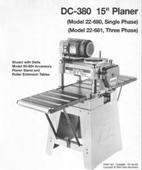 DESCRIPTION 1 Pan Head Screw M6x12 P25-200H-1, 6 & 8 JOINTERS WITH SPIRAL CUTTERHEAD MODEL: KC-75FX (6 Jointer) MODEL: KC-85FX (8 Jointer) INSTRUCTION MANUAL COPYRIGHT 2007 ALL RIGHTS RESERVED BY KING CANADA TOOLS INC. WARRANTY INFORMATION 2-YEAR LIMITED, SS 14 Oscillation Vertical Spindle Sander Manual LAGUNA TOOLS 2072 Alton Parkway Irvine, California 92606 Ph: 800.234.1976 www.lagunatools.com Part No. Description Size Qty 1JWP15H-001 Head Casting1 2TS-1525021 Set Screw M10x128JWP15DX-CA Cutter Head Assembly (Index, ST1007/ST1012 PARTS ST1007 Main Breakdown 30-7 30-8 30-10 30-9 30-1 30-3 30-6 30-2 30-4 30-5 82 83 84 77 78 79 80 30 60 59 58 62 64 61 46 44 63 66 65 55 56 26 45 27 45 27 25 43 37 41 50 42 72 73 51 53, VARIABLE SPEED WOOD LATHE Model DB900 INSTRUCTION MANUAL 1007 TABLE OF CONTENTS SECTIONPAGE Technical data.. 1 General safety rules.1-3 Specific safety rules for wood lathe..3 Electrical information.4, MODEL MC1100B VARIABLE SPEED WOOD LATHE INSTRUCTION MANUAL Please read and fully understand the instructions in this manual before operation. Main Model G0771Z (Mfd. 60178-0127 Ph:815-899-6670 Fax:815-899-1918 Thank, 1 1 2 2 3 3 82mm (Max) 12mm (Max) 12mm (Max) 6mm (Max) 4 4 5 6 8 6mm (Max) 0.5 0mm 1 5 6 7 7 8 9 9 A = B 10 11 12 D B 1 13 14 15 0 C A D E 16 17 18 F G D B N H J G I K 19 A 20 G L 21 C K 1mm L M 1mm 22, Operating Instructions and Parts Manual 22-inch Planer Models 201 and 201HH WALTER MEIER (Manufacturing) Inc. 427 New Sanford Road LaVergne, Tennessee 37086 Part No. M-321442 Ph. DESCRIPTION KEY NO. Tapping Screw (W/Flange) 10 Gear Cover Ass'y. 01530 516926 Fax. W' ' " " 1 3~j ;, II,Ll '~{l tl ==0 fl~~ ~~f,a~11j~~~'--~' ~~~$~-et~'~~s~f8~1~ Fig2 Table Extension Roller Assembly 1 Locate two boxes containing the table extension roller assemblies Also find bag containingsix M8 x 12 set screws, six M8 x 20 hex cap bolts, and six M8 washers 2 Thread six set screws (A, Fig 3) into the table extension rollers so that they are fiush with the surface that faces the machine Fig3 3 Attach table extensionrollers to the planer table using six M8 x 20 hex cap bolts (B, Fig 3) and six M8 fiat washers 4 Place a ~traight edge through the planer so that ~ITliesa-crDssbothtableancrrollers',SeeFrg:4"-~w, 5 Using the hex cap bolts (A, Fig 4) and set screws (B, Fig 4), adjust each table extension, 9 roller The straight edge should rest evenly across the table and rollers Electrical Switch Assembly 1 Removetwo M6 x 12 (A,Fig 5) hex socket cap screws from the left sideof the planer 2 Attach the switch box assembly (B, Fig 5) to the side of the planer with two M6 x 12 hex socket cap screws through the switch plate (already attached to the switch box) Dust Chute Assembly 1 Attach the dust chute to the cover using three hex cap bolts, and three washers (A, Fig 6) Attach the dust chute to the head casting with three hex socket cap screws, and three lock washers (B, Fig 6) Fig5 A Knife Setting Gauge 1 Slide gauges onto both endsof the gauge bar and insert with four e-rings Attaching Handwheel 1 Peel off paper backing onthe direction indicator and press firmly ontothe centerof the handwheel hub 2 Tap the key stock intothe key slot on the worm gear shaft 3 Slide handwheel(a Fig7) onto shaft Make sure notch in handwheellines up with and engages key stock 4 Fasten handwheel to the shaftwith one M10 washer and one M10 hexnut (B, Fig 7) Fig ', 11 ',- ~,----_ Electrical Connections The JWP-15CS planer is rated at 230V This machine is intended for use on a circuit with an outlet that looks like the one illustrated in Fig 8 The machine must be hard wired to the electrical circuit or connected to a plug with a grounding prong that looks like the prong illustrated in Fig 8 Make sure the tool is connected to an outlet having the same configuration as the plug No adapter is available or should be used with this machine If the machine must be reconnected for use on a different type of electrical circuit, the reconnection must be made by qualified service personnel; and after reconnection, the tool must comply with all local codes and ordinances (\ \ \ ~\ \\,~~ " J'l Grounding / Prong / Fig8 ( ~\ '--:J r;;-:-\ \~,0 'o<-&-_war~ingi;'j;t'j',;"~i~#,/e:t' All el~ctricat:poh~ecti6n_s;must be(dgji"e :u";;qualifieidservice pers:onhell%:,;~\ '"--"' Failure to comply may result in serious injury! JOINTER by INVICTA. The Model G0453P is the same machine as the Model G0453Z but with a "cool" new look and, MODEL T27697 & T27699 6" & 8" HELICAL CUTTERHEADS INSTALLATION INSTRUCTIONS For questions or help with this product contact Tech Support at (570) 546-9663 or techsupport@grizzly.com These indexable insert, -83- Main 29 30 31 34 35 36 37 38 39 40 41 42 43 44 45 46 47 48 49 50 51 52 53 54 55 56 57 58 61 62 63 64 65 66 67 68 69 70 71 72 73 74 75 113 96 90 91 92 93 95 96 97 98 100 101 102 103 104 105 106 109, MODEL T27696 12" HELICAL CUTTERHEAD INSTALLATION INSTRUCTIONS For questions or help with this product contact Tech Support at (570) 546-9663 or techsupport@grizzly.com Introduction The Model T27696 indexable, Machinery & Tooling at its best! V:J c-s J- )0- D79C ---G-~Cy ~~-,-,c;0,if-- '\x,q 0' ~ )~ -z\)j ' ~- - '-'--'--' ---, 37 f ~ f j if Ii' I Table Assembly \ i~,~ ')~ mm "'''''' -"'-"''''_''m ' ~ ''''-''~''''''''''',, '''''''---' - 19, 39 ~",,,~~_"~~~~~-~ ~~, Table Assembly 1 JWP15H-101 MiddleTable 1 2 JWP15H-1 02, Roller " " """'"'''''''''' 2 3 BB-608Z Ball Bearing " 4 4 JWP15H-104 Eccentric Shaft, """",,"""'''''''''''''''''''''''''''' 4 5 TS Set Screw M6x10-12 ""'"'''''''''''''''''''' 4 6 JWP15H-106 Threaded Lock Bushing, ' 2 7 JWP15H-1 07 " Lock Bolt, 2 8 JWP15H-108 Lock Bushing, 2 9 JWP15H-1 09 Knob ""'''''''''''''''', 2 10 TS Hex Socket Cap Screw M6x PJ Roller Frame " 2 12 JWP 15H-112 " Roller "'"'''''''''''''' 6 13 JWP15H-113, Roller Bushing, JWP15H-114 Shaft '"'''''''''''''''''''''''''''''''''''''' 6-15 TS Hex Head Bolt M6x TS Washer "'''''''''''''' 1/4 "'"''''''''''''''''''''''-''''''''' TS , Hex Cap Screw M8x " 6 18 TS , Washer M TS Set Screw M8x JWP15H-230 Cut Limit Pointer """""'''''''''''''''''''''''''''''''''' 1 21 JWP 15H-231 Rivet, 2x5 2 _' '_-_",,_", '-~ ~-;~, ~-,-----_-, 43 Stand and Motor Assembly 1 PJN-S01 Base """"""'" 1 2 JWP15H-404 " Support Bar """"""" 2 3 JWP15H-406 Motor Bracket """"""'''''''''''''''''''''''''''''''' 1 4 TS Set Screw M6x10x6 """"""""'''''''' 4 5 JWP15H-408 Collar "'''''''''' 1 6 ""'''''' JWP15H-409 Adjusting Bolt 1 7 TS Nut M1Ox TS : Washer 1/2 2 9 JWP 15H-412 Motor 3HP 1 10 TS Hex Cap Bolt M8x125x TS Washer M8 '"'''''''''''''''''''''''''''''''''' TS Hex Nut M8x TS , Hex Cap Bolt M8x EB-A09 " Washer 5/16x16x JWP 15H-418 " Power Cable "'''''' 1 16 PAG-M02, Motor Cable ""'"'''''''''''''''''''''''''''' 1 17 PG-M02 Jet Plaque E-A200 Flat Head Screw " M5xO8xx6 ""'''''' EA-E06A " Flat Head Screw M6x1 Ox PJH-S02 Door '"'''''''''' 1 21 HC Hex Nut ""'"'' M1Ox15 "'" ""'''''''' 1 22 H E Flat Washer M10 "'''''''' 1 23 PJN-S02 Foot Brake,, CA-H16B Hex Cap Screw 3/8x16x2 1/ PJE-S05 Wheel ", DD-B09 Hex Nut """ 3/8x SMA-L05 Strain Relief Bushing 2 28 PJN-S03 " Shaft 1 29 PG Spring " 2 30 HGO10911 Spring Pin on 4x HA Set Screw M6x1x6 ""'''''''''''''''''''' 2 32 PJN-S04 EccentricCarn ~ FK-C23 Key 5x5x " -'- -- ", 45 Electrical Schematic ~ U 4: -! '"' MODEL W1.0X305A(12 ) MODEL W1.0X610A(24 ) HAND BENDING BRAKE ASSEMBLY&OPERATING INSTRUCTION, G0513X2 Main. Failure to follow the SAFETY RULES listed, OWNER S MANUAL JWP-208 Planer WMH TOOL GROUP Consumer WoodworkingDivision 2420 Vantage Drive Elgin, IL 60123 Ph: 888-804-7129 Fax: 800-274-6840 E-mail: jet@wmhtoolgroup.com M-708528 8/03 www.wmhtoolgroup.com, MODEL T10130/T10126 6" & 8" SPIRAL CUTTERHEAD INSTRUCTIONS The Model T10126/T10130 indexable insert spiral cutterheads are designed to replace straightknife cutterheads from the Grizzly jointer Models, INDUSTRIAL RIP FENCE SYSTEM MODELS KRF-10/30L12-30 CONTRACTOR SAWS KRF-10/52L12-52 CONTRACTOR SAWS KRF-100/T50L12-50 CABINET SAWS INSTRUCTION MANUAL COPYRIGHT C 2000 ALL RIGHTS RESERVED BY KING CANADA, 01936 Variable Speed Cast Iron Midi Wood Lathe Please read and fully understand the instructions in this manual before operation. Specification 4 5. Keep this manual safe for future reference. G0513X2 Main 23 55 22 48 17 17-1 17-2 21 7 17-3 17-2 17-4 24 17-5 18-5 22 24 21 55A 50 8 9 49 11 12 13 14 15 47 16 10 46 45 3 44 43 39 38 37 39 40 32 33 36 42 34 35 2 25 28 18-4 18-2 18-3 31 30 29 18-1, Electric Router FOR HELP OR ADVISE ON THIS PRODUCT PLEASE CALL OUR CUSTOMER SERVICE HELP LINE : 0509 500400 THE MANUFACTURER RESERVES THE RIGHT TO ALTER THE DESIGN OR SPECIFICATION TO THIS PRODUCT WITHOUT, TP00 OWNERS MANUAL INCH THICKNESS PLANER WITH LEGSET For Your Safety: Read all instructions carefully Save this manual for future referenece SP Printed in Taiwan Parts List for " Thickness Planer Model, Thank you for considering "cutting edge technology." Model BR-3 Blade Reconditioner EQUIPMENT TABLE OF, JPM-13CSX PLANER XM XT 230/50/1 400/50/3 PARTS LIST ERSATZTEILLISTE LISTE DE PIECES, PARTS. 1. Owners Manual. For Your Safety: Read all instructions carefully Save this manual for future referenece, Thank you for considering "cutting edge technology.
 : MI-76100 MI-76150 OPERATING MANUAL RULES for SAFE OPERATION MAGNUM INDUSTRIAL MI-76100 and MI 76150 DRILL PRESSES To help ensure safe operation, please take a moment to learn the how to operate, MODEL T27451/T27452 15" & 20" SPIRAL CUTTERHEAD INSTRUCTIONS For questions or help with this product contact Tech Support at (570) 546-9663 or techsupport@grizzly.com The T27451 15" & T27452 20" indexable.
- Brilliance Laser Ink Alternative
- Chalkboard Stickers Walmart
- Sentry Air Systems Ss-400-pfs Manual
- 12 Gauge Copper Wire Home Depot
- Toronto Blue Jays Black Red Leaf 59fifty Fitted
- Cow Manure For Sale Near Bradford
- 1601 Maple Street Carrollton, Ga 30118
- Threaded Inserts For Magnesium
- Golden Boat Lift Maintenance
- Vallejo Model Air Colour Chart
- Kitchen Dustbin Drawer
- Aluminum Structural Pipe Fittings
- Fabric Wholesale In Bangalore
- Aroma Bead Depot Coupon
- Hotel Louisville Address
- Floral Halter Midi Dress
- Stanley Hose Reel Sam's Club