For air valves, atmosphere is the tank, so exhaust piping is usually unimportant. A two position, single solenoid, spring return valve is sufficient for this operation. Using 2-way valves
The problem comes when the 2-way returns to normal at the end of cycle. An inching circuits repeatability is usually not closer than 1 in. With the pilot-operated check valve after the counterbalance valve, the counterbalance valve must have an external drain. If the cylinder needs to float while blocking pump flow, use the center condition shown in Figure 8-40. Even if pilot pressure could go high enough to open the pilot-operated check valve, the cylinder runs away and stops. If the valve is solenoid pilot-operated, the supply to the pilot valve usually comes from port #1. About 90% of air circuits use this type of valve. Energizing and holding a directional valve solenoid causes the cylinder to move. If the valves are not blocked, the tank must be drained when changing a hydraulic component.
(Some suppliers call their 5-way valves, 5-ported 4-ways.") Placing the pilot-operated check valve in the line after the counterbalance valve would require neither an external drain nor decompression feature. Pump flow to the cylinder cap end builds pressure in the pilot line to the rod end of the pilot-operated check valve, causing it to fully open. This requires a 3-way valve. Speed control mufflers give individual meter-out speed control in each direction of travel. Another flow condition is the diverter valve shown in Figure 8-10. An all-ports open center condition directional valve unloads the pump and allows the actuator to float as shown in Figure 8-38.
Once this normally closed valve shifts, it passes a signal on to continue the cycle. When using an on-off type solenoid valve, a fast moving cylinder stops abruptly when the directional valve centers. Poppet valves usually only take pressure at one port. Figure 8-44 shows a tandem center valve. Pilot-operated check valves
Connecting pressure oil to both cylinder ports and to each other regenerates it forward when the valve centers. 2022 Endeavor Business Media, LLC. The reason this might happen is the pilot piston sees backpressure from the reverse flow outlet port. 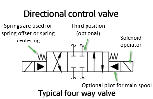 Valve operators come in different types. Use this spring-centered, single solenoid valve in control circuits for special functions. An external force can pull against the trapped oil in the cylinder and cause damage or failure without relief protection. Figures 8-54 to 8-61 show another reason for using dual pressure inlets. In the crossover or transition condition it causes very little shock. If both inlet pressures are too low to operate the valve, plumb an external pilot supply from the main air system. It takes about 120 psi on the 10-in.2 area to slow the cylinders rapid retraction. This pressure would have been about 1200 psi while the cylinder was retracting, but quickly drops to zero when the directional valve centers. The heavier the weight and the slower the cylinder speed, the longer the pause. Figure 8-66 shows the symbol for a standard pilot to open check valve. Most spool-type air valves come in a 5-way configuration. Normally a check valve is not thought of as a directional control valve, but it does stop flow in one direction and allow flow in the opposite direction. 1 or Pr. The most common limit valve is a miniature 3-way like the one shown in Figure 8-30. See Figures 8-34 to 8-36 for some uncommon uses of 4-way directional control valves. The pilot-operated check valve in the line to the rod end opens by pump flow like any check valve. In Figure 8-53, the 5-way has a dual inlet instead of dual exhaust. This load-induced pressure holds against the poppet in the pilot-operated check valve, forcing it closed. If there is a restriction causing high backpressure in the reverse flow outlet port, a standard valve may not open when applying pilot pressure. When a cylinder retracts to pick up another part, it often has to go too far to make sure it is behind the part. There are some circuits that need the positive shut off of a check valve but in which reverse flow is also necessary. Changing the pilot line in the field with assistance from the suppliers catalog is quite easy.
 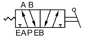 At first sight it looks as if this circuit might work. Deenergizing the solenoid or retracting, lets the valve shift to home position, and the cylinder retracts from outside forces.
  Every time a cylinder cycles, the lines to both ports fill and exhaust. A water faucet allows flow or stops flow by manual control. Energize and de-energize all four valves simultaneously to cycle the cylinder and keep from wasting fluid. Notice the directional valve has A and B ports open to tank in the center condition. Some manufacturers use dual 3-way valves to conserve air.
  When the inlet is blocked in the at-rest condition, as shown in Figure 8-1, it is referred to as "normally closed" (NC). This sets a pressure differential across the piston before the valve shifts. Because oil must return to tank, it is convenient to connect the dual tank ports to a single return port. Hi-L pump circuits, reverse free flow bypass for flow controls, sequence valves or counterbalance valves, and multi-pump isolation, to name a few. Low backpressure from the check valve makes the cylinder creep forward at low power so the cylinder is in contact with a part before the next cycle starts. A double-acting actuator requires a 4-way valve. Use a spool type directional control valve in this type of circuit. In the past, to get this configuration, you only had to wire one solenoid of a double-solenoid, three-position valve. Figures 8-41 to 8-46 show several commonly used 4-way hydraulic valve center conditions. The counterbalance valve keeps the cylinder from running away no matter the flow variations, while the pilot-operated check valve holds it stationary when stopped. According to valve size and inlet air flow, the cylinder might not extend if just energizing the (NC) valve.
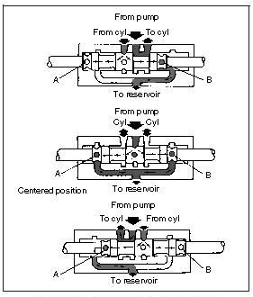
  Now the load drops rapidly until air pressure in the cap compresses to approximately 120 psi. If it is only necessary to keep the cylinder from moving in one direction, one pilot-operated check valve will suffice. The cylinder sits still unless there is an outside force trying to move it. In normal condition, fluid in the control circuit exhausts through the exhaust port. When the valve shifts to retract the fully extended cylinder, there is another problem. Lines to the boxes show flow to and from the valve, while lines with arrows in the boxes show direction of flow. This oscillating movement would continue until the cylinder competes its stroke. Using 4-way valves
Some check valves have a removable threaded plug in them that may be drilled to allow controlled flow in the reverse direction. In Figure 8-78, rod end pressure is at 3565 psi because pilot pressure continues to climb. As pilot pressure builds to open the poppet, it also pushes against the full piston area of the cylinder. Open crossover stops shock while the spool shifts, while a closed crossover reduces actuator override travel. A 4-way valve pressurizes and exhausts two ports interdependently. Instead of the cylinder retracting after the solenoid de-energizes, it stays in the extended position. A check valve with a low-pressure spring, called an tank isolation check valve, on each return line allows free flow to tank, while blocking flow out of it. A 3-position, 4-way valve stops an actuator or allows it to float.
Now the load drops rapidly until air pressure in the cap compresses to approximately 120 psi. If it is only necessary to keep the cylinder from moving in one direction, one pilot-operated check valve will suffice. The cylinder sits still unless there is an outside force trying to move it. In normal condition, fluid in the control circuit exhausts through the exhaust port. When the valve shifts to retract the fully extended cylinder, there is another problem. Lines to the boxes show flow to and from the valve, while lines with arrows in the boxes show direction of flow. This oscillating movement would continue until the cylinder competes its stroke. Using 4-way valves
Some check valves have a removable threaded plug in them that may be drilled to allow controlled flow in the reverse direction. In Figure 8-78, rod end pressure is at 3565 psi because pilot pressure continues to climb. As pilot pressure builds to open the poppet, it also pushes against the full piston area of the cylinder. Open crossover stops shock while the spool shifts, while a closed crossover reduces actuator override travel. A 4-way valve pressurizes and exhausts two ports interdependently. Instead of the cylinder retracting after the solenoid de-energizes, it stays in the extended position. A check valve with a low-pressure spring, called an tank isolation check valve, on each return line allows free flow to tank, while blocking flow out of it. A 3-position, 4-way valve stops an actuator or allows it to float.  The circuit in Figure 8-70 shows a horizontally mounted, non-leaking cylinder, positively locked in place any time the directional centers. The circuit in Figure 8-65 also shows an anti-cavitation check valve for the cylinder with a relief valve to protect it from over pressure. When a cylinder has a load, trying to extend it causes load-induced pressure. Figure 8-27 shows four 2-way valves piped to operate a double-acting cylinder. This valve shifts from an actuator moving flow path to center condition for certain special circuits. Figure 8-36 shows how to pressurize both ends of the cylinder when a 4-way valve centers. Figures 8-5 through 8-10 show schematic symbols for 3-way directional control valves. It is possible to inch an air circuit if accuracy and repeatability are not important. The pause comes from weight pushing down along with force from air pressure on the cylinder rod end. Heat exchangers, filters, and low-pressure transfer pumps often need a low-pressure bypass or relief valve.
 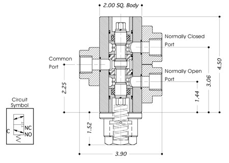 Some manufacturers make a check valve with an adjustable spring, for pressures up to 200 psi or more. Add flow controls or a counterbalance valve to complete the circuit when there is weight on the rod. Figures 8-22, 8-23, and 8-24 show some uses for 2-way directional control valves.
Even with some spool type counterbalance valves, the cylinder still drifts. Mufflers not only make the exhaust quieter, but throttle the exhaust, which in turn controls cylinder speed in a meter-out circuit. In figure 8-59 to 8-61, the cylinder strokes smoothly and quickly in both directions with dual-pressure valve. The cylinder would extend with a decompression poppet, but at a very slow rate. Faster travel speeds give less control.  The following will describe how pilot-operated check valves can cause problems in some applications. Energizing the solenoid on this valve stops fluid flow. A check valve with a 25-125 psi spring makes an inexpensive, non-adjustable, flow path for excess fluid. Shifting the 2-way valve, or extending, sends fluid to the cylinder cap end and it extends. The simplest directional control valve is the 2-way valve.
 A cylinder with these conditions falls and stops all the way to the work unless it meets enough resistance to keep it from running away. This flow control valve is not pressure compensated. Hydraulic motors always have internal leakage so the circuits shown here will not hold them stationary. A pair of 2-way valves at each cylinder port gives a power stroke in both directions. The float center valve of Figure 8-43 allows the actuator to float while blocking pump flow. Vertically mounted cylinders with down acting loads always creep when using a metal-to-metal fit spool valve.
 The following images show symbols of pilot-operated check valves that allow reverse flow. A 3-way valve has three working ports. Figure 8-41 shows an all-ports-open center condition valve. The extra hydraulic pressure pushes harder against the pilot-operated check valve poppet, making pilot pressure increase even more. Figure 8-65 shows some other applications for check valves. Normally, input air goes to the center port of the side with three ports.
  Make sure the valve is capable of backpressure at the tank port. 5-way directional control valves
The weight-to-cylinder force ratio and the rate of cylinder travel speed control the length of pause. It requires approximately 500 psi pilot pressure to open the pilot-operated check valve with 1650 psi against the poppet. A 2-way valve in Figure 8-23 operates a one-direction motor with an open exhaust in the motor housing. Figure 8-6 depicts an all-ports-blocked, 3-way, 3-position valve. To make a high flow 2-way valve from a 4-way valve try the circuit shown in Figure 8-34. In either case it provides pilot pressure to shift the directional valves when a new cycle starts.
Make sure the valve is capable of backpressure at the tank port. 5-way directional control valves
The weight-to-cylinder force ratio and the rate of cylinder travel speed control the length of pause. It requires approximately 500 psi pilot pressure to open the pilot-operated check valve with 1650 psi against the poppet. A 2-way valve in Figure 8-23 operates a one-direction motor with an open exhaust in the motor housing. Figure 8-6 depicts an all-ports-blocked, 3-way, 3-position valve. To make a high flow 2-way valve from a 4-way valve try the circuit shown in Figure 8-34. In either case it provides pilot pressure to shift the directional valves when a new cycle starts.  The symbol in Figure 8-68 shows a pilot-operated check valve with an external drain for the pilot piston. Figure 8-77 shows the start of this condition. Figure 8-4 shows a cam-operated valve. Energizing and holding a directional valve solenoid causes the cylinder to move. This means, with a dual pressure inlet, pilot supply must come from some other source. When the tank is higher than the pump or directional valves, always install some means to block flow lines for maintenance. This is another common center condition for fixed volume pumps. A tandem center valve lets the pump unload while blocking the cylinder ports. Here it is in the line feeding the directional valves, other times it is in the tank line. The anti-cavitation check valve has no effect during any other part of the cycle.
 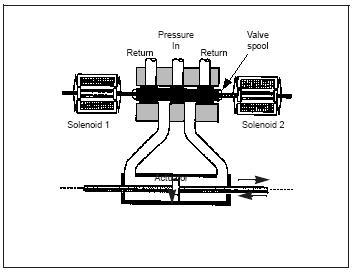 However, this void can cause erratic action when the cylinder cycles again, so install an anti-cavitation check valve. The solenoid slash and energy triangle in the operator box show the valve has a solenoid operated valve piloting a pilot-operated valve. However, the restriction could cause fluid heating and slow cycling, and would need frequent adjustment to maintain optimum control. After the air exhausts to the lower pressure, PR.1, the shuttle shifts and low pressure holds in the system. Directional control valves perform only three functions: These three functions usually operate in combination. As discussed before, reducing air pressure at the cylinder uses less compressor horsepower. Fixed volume pumps use this center condition.
  If a void in the cap of the cylinder is no problem then an anti-cavitation check valve is unnecessary. Following are schematic symbols for commonly used directional control valves. Adding an externally drained pilot-operated check valve between the counterbalance valve and the cylinder holds it stationary. This valve has a third position but there is no operator for it. To duplicate the 2-way function, block the exhaust port of the 3-way valve. This move eliminates the need for externally drained pilot-operated check valves. Palm-button-operated 3-way diverter valve.4-way directional control valves
Using this port connection arrangement consistently makes it is easy to wire the circuit because the electrician knows A solenoid extends the cylinder while B solenoid retracts it. Also, a lot of 2-way hydraulic valves only stop flow in one direction, so they are useless in a bi-directional flow line. Palm-button-operated 3-way diverter valve. However, in the past few years, poppet type slip-in cartridge valves have been operating large bore hydraulic cylinders this way. Figure 8-13 shows another unusual 4-way configuration. Placing a flow control after the pilot-operated check valve causes backpressure against its pilot piston and could keep it from opening at all. The center condition of a 3-position valve can unload a pump, open actuator ports to tank for free movement, block actuator ports to stop movement, give regeneration, or work in combinations of these functions. The 5-way selector valve and shuttle valve in Figure 8-50 works where a 3-way selector may not. Figure 8-52 shows the normal hookup of a 5-way valve. The load lowers smoothly and safely without lunging or bouncing, as fast as cap end air exhausts. The reason for this pressure drop is leakage past the counterbalance valve spool, which is the reason for adding the pilot-operated check valve. This particular example is (NC).
If a void in the cap of the cylinder is no problem then an anti-cavitation check valve is unnecessary. Following are schematic symbols for commonly used directional control valves. Adding an externally drained pilot-operated check valve between the counterbalance valve and the cylinder holds it stationary. This valve has a third position but there is no operator for it. To duplicate the 2-way function, block the exhaust port of the 3-way valve. This move eliminates the need for externally drained pilot-operated check valves. Palm-button-operated 3-way diverter valve.4-way directional control valves
Using this port connection arrangement consistently makes it is easy to wire the circuit because the electrician knows A solenoid extends the cylinder while B solenoid retracts it. Also, a lot of 2-way hydraulic valves only stop flow in one direction, so they are useless in a bi-directional flow line. Palm-button-operated 3-way diverter valve. However, in the past few years, poppet type slip-in cartridge valves have been operating large bore hydraulic cylinders this way. Figure 8-13 shows another unusual 4-way configuration. Placing a flow control after the pilot-operated check valve causes backpressure against its pilot piston and could keep it from opening at all. The center condition of a 3-position valve can unload a pump, open actuator ports to tank for free movement, block actuator ports to stop movement, give regeneration, or work in combinations of these functions. The 5-way selector valve and shuttle valve in Figure 8-50 works where a 3-way selector may not. Figure 8-52 shows the normal hookup of a 5-way valve. The load lowers smoothly and safely without lunging or bouncing, as fast as cap end air exhausts. The reason for this pressure drop is leakage past the counterbalance valve spool, which is the reason for adding the pilot-operated check valve. This particular example is (NC).  This valve is the pilot operator for hydraulically centered directional valves or normally closed slip in cartridge valves. Also use dual inlet piping to make an air cylinder operate quickly and smoothly. For a full time regeneration circuit, pipe the 4-way as shown in Figure 8-35. The boxes show the function of the main or working spool that controls the actuator.
- Hemingways Nairobi Location
- Antibiotic Ointment For Rabbits
- Magnetic Septum Ring Claire's
- Coleman Dark Room 8 Person Tent
- Caudalie Moisturizing Toner 400ml
- Strathmore Watercolor Cards
- Acrylic Engraving Near Me
- Hotel Harrington, Washington Dc Bed Bugs
- Kate Somerville Retinol Cream
- Mens Slim Fit Fatigue Pants
- Postgres Vs Sql Server Data Warehouse
- Bissell Powerforce Bagged Vacuum Belt
- Flow Meter Symbol Autocad
- Unfiltered Honey Benefits
- Garden Hose O-ring Walmart
- Flattering Black Dress For Size 14
- Climbing Arch Pillow Pattern