8mm: BOTTOM INSIDE / INLET: Drill (2x) 8mm-holes where you made a 8mm-mark before. Now that you know how long to cut your rubber pieces, make three more of them and place them on the front hatch like I did in the picture. While the box dries you can already make it some "feet.". While you tighten them, grab the cable, so that it does not turn so much together with the tighteners. You need to get the cable through the cable holder and in there through the little hole in the rubber piece that we installed in the previous step. 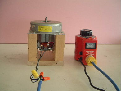
Follow it with your finger or a sharpie marker around the hose to see if it is a single thread or a double thread.
Attach "PP11_Front-Hatch-Gasket-Holder" and (4x) rubber hatch-gasket-pieces to the front hatch with 8 screws and washers. Rechargeable Battery Operated Suction Cup and mounting system. Now we will prepare the electrical components.
Now we need to drill 2mm-holes into those boards.
FRONT INSIDE / REAR INSIDE: Align the printed parts "PP11_Front-Hatch-Gasket-Holder" and "PP1009_Rear-Hatch-Gasket-Holder" with the marks on the boards.
The screw holes lie on the vertical mark. Where did the printed handle holder (PP10) go?
The project is from 2019, and Krahmer now has his MFA in Industrial Design. Now put the small filter we made earlier on top of the grid. The screw holes in the parts' corners lie on the diagonal marks.
Place the INLET-board on the table with the gluey sides pointing towards the LEFT and RIGHT boards. As we did earlier, drill some 2mm-holes into the wood where the lines meet. The most common power-switch inside vacuum cleaners looks like the black and white models in the last three pictures. Remove three cable-shoes from the remaining cables and keep them. Cut your 18mm thick wood to the sizes given in the technical drawing.
Switches like that are often labeled 80C NC 10A (80C, normally closed, 10 ampere) or KSD80. Glue and screw the BOTTOM-board to the "H.". Tie the bag to the bag-coupling (PP12) on the front hatch with a bow.
In the next step we will finally connect the motor and close the circuit. If the glue of the box has already dried for some time (check the description on the glue you are using), you can remove the clamp and the four screws in the corners of the bottom. does the trick perfectly. Contact Hackaday.io
Now mark the boards in the lower left corners with a pencil as shown in the pictures. The 2000W-power-regulator (see previous step) works with PP14-s07 and the 4000W-version withPP14-s10.
If it doesn't, you can rotate the motor adaptor on the celtic cross.
You can cheat by using PP1001, PP1005 and PP1007 as templates again. If the turbine of your motor has a very inconvenient shape (for example a protruding metal collar exactly at the height where the motor holders end) that prevents you from mounting it properly, try to slide some extra rubber-bits under the rubber-padding of the motor holders.
MOTOR: Align the printed part "PP1001_Turbine-Gasket-Holder" with the marks on the board.
Vacuum table for CNC machines made out of aluminium with some useful features, Revive a B&D Dust Buster by replacing the NiCd/NiMH battery with 18650 cells, Open Source Freakin' Scanning Electron Microscope, DIY Beam-on-Target Fusion Particle Accelerator, NLA: DeWalt DW708 Mitre Saw "Dust Extactor", Old Russian VFD module converted into a clock, Open Source Turbomolecular Pump Controller, The DIYson, an open source Cyclone vacuum cleaner, Black & Decker - Dust Buster: battery replacement. The screw holes lie on the diagonal marks. Two of the screw holes lie on the vertical mark.
LEFT / RIGHT / INLET Flip the boards upside down sideways.
Put the last filter into "PP21_Central-Filter-Holder_Lid. You can also tighten the cable-tighteners now.
To do so, use two small boards as guides to simulate the walls that will surround the MOTOR-board in the motor-chamber later, Step 41: Trace the Screw-holes for PP1001.
Attach "PP14_Electronics-Compartment_Upper-Part" with 4 screws and washers. The screw holes in the parts' corners lie on the diagonal marks.
In the next steps we will mark the positions for those small screw-holes.
Read through the next seven steps and put the box together without glue and screws and start putting it together for real when you have an idea how it needs to be assembled.
Now trace the two screw holes with a pencil.
-mark are visible in the lower right corner like in the drawing.
Step 173: Installing the Power-Switch & Button. Rub some extra glue on the areas where the foil ends to seal them. Now file of fthe edges until you are left with nice chamfers and the feet are done!
Cut off two pieces of rope, each 120cm long. Stack the pieces on top of each other, make sure that the holes are aligned and pin the stack together. Do not touch the hatched areas around the edges yet. One goes in from the side and one from the back (first picture).
To make it even clearer, I added the hose-size-range to each file-name like this: PP02-d38-PETG_2020-02-02_tenok_Hose-adapter_double-spiral_, Making the Box Preparing the Boards 1/2.
Preserve that feeling a little longer because we still need to make some parts before the final assembly and we start by making rubber shock absorbers and gaskets from bicycle tube.
Use a compass do draw a 143mm-circle in the center of this board. REAR INSIDE / FRONT INSIDE / MOTOR: Use a pencil to connect the corners of the square pieces with a line. You can use a coin as screwdriver.
When the glue has dried properly, you can apply a finish to the wooden parts. Those would require a special adaptor, but they seem to be not so common and I did not find one yet. Refer to the picture to make sure you arranged them correctly.
For the ABS parts you should put an enclosure around the printer / print-chamber to avoid warping.
There are multiple positions in which it can be mounted. .
If you cannot slide them in completely, work the parts with a utility knife or similar.
Why does the wooden handle suddenly look strange? Apply glue evenly to the wall that separates the motor chamber from the bag chamber. Essentially the two parts are identical, except for the hole where the power regulator is mounted because the bigger one also uses a bigger potentiometer with a bigger shaft. Put the rubber square in the printed turbine-gasket-holder (PP1001) and trace the hole in the middle on it. instructions online about making such a bag, so I decided to just link one of them here, ### PLEASE NOTE: DETAILED PARTS LIST BELOW! Step 102: Place the Last Aluminum Foil Piece. Lay the cut-open bicycle tube flat on the table. Now cut out the circular filter you traced on the micro-filter-fabric. Reward yourself by vacuuming the room!
Repeat the previous step 5 times, so you have six rear shock aborbers in total. The guides on the outside of PP12 need to be aligned with the diagonal marks.
Make marks to drill a 20mm-hole and two 30mm-marks. and also the scavenged power-switch and the power regulator module. Slide the power-switch into PP14 so that it sits under PP20, 4.)
It is possible to print the PETG-parts from PLA instead, but they become less flexible / break more easily.
Attach "PP06_Cable-Holder-central-wall_Outer-Part" with two screws and washers. From the coarser motor-filter-fabric we make two more circular filters: One is 125mm and the last filter is quite tiny with just 24mm. Attach "PP08_Cable-Holder-bottom_Outer-Part" on the bottom inside the box with two screws and washers. Now trace the two screw holes with a pencil. Attach the other two cables that go to the motor chamber to the "OUT"- terminals.
Again the 8mm are measured from the surface we marked initially. cable-shoe) and keep it.
PLEASE NOTE: Most office chair castors have 11mm-shafts, but some have 10mm-shafts.
Step 35: Trace the Screw-holes for PP1007. That's why there are also a lot of instructions online about making such a bag, so I decided to just link one of them here. You can of course also look for another drawstring-bag-tutorial and follow that one I just did a quick search and there might be better ones. There are two parts where you need to choose a size, depending on which components you have scavenged / bought, namely print-parts PP02 (hose-adaptor) and PP14 (electronics compartment, upper part). Take a close look at the two parts to see how you need to orient the grid so it fits into the base. There are two electric components you need to buy. This step is especially important when you used coniferous wood like me as it can leak resin when it gets warm and you do not want resin to ooze into your motor, when the vacuum cleaner gets a little warmer. The screw holes lie on the horizontal and vertical marks. Using light to make your object look just right is both art and science, so we found a pro who can break it down for you: McKay Nilson. I was born in NYC and figured Id die there, but a few years ago I abandoned New York to live on a farm in the countryside with my wife. For drilling into the side surfaces it's helpful to put up some sort of guide, to align the board to it like I did in the photo, After drilling the boards are ready for assembly.
Put one of the cable tighteners (PP09) on the power cord. Pull the cord arount the two cord-pins (PP04) on the front hatch.
flip them lengthwise or you will run into problems.
All files you need to print can be downloaded from Thingiverse via this link: https://www.thingiverse.com/thing:3710521. BOTTOM INSIDE / TOP INSIDE: Draw vertical lines and marks positioned as in the drawing. The guides on the outside of PP23 need to be aligned with the horizontal and vertical marks. Heat-sensor-switches can be bought with different temperature-ratings and for Tenok we need one that activates at 80C (or in more precisely between 72 and 88 C because of tolerance). Im a lapsed industrial designer. Maybe helix is the correct word, but let's stay with spiral for simplicity. You need to choose the version of PP02 that fits the hose you scavenged.
(If your rubber sheet was to short to cut proper squares, rotate every second piece, so that the stack becomes squareish).
On the third picture I connected them to give you an idea how the circuit looks. Before glueing the "H" together, also put glue on the surfaces of the three boards that point upwards.
The guides on the outside of PP12 need to be aligned with the diagonal marks. No worries, we will just sand the marks off in the end and they will not be visible on the finished vacuum cleaner. The knots of the thread can later rest in the small pockets of the printed turbine-gasket-holder (PP1001). TOP OUTSIDE: Make marks to drill a 20mm-hole and two 30mm-marks. For those smaller shafts you should also just drill a 10mm-hole (otherwise you have to wind some tape around them, when attaching them). PP20 only fits one way: When you look closely at the picture you can see that it has a small recess on one side. For this project you will need the tools in the picture that are listed below. Add two vertical marks on the center of the board. In the first picture I circled all positions where you need to drill a 5mm-hole. If you have no possibility to cut the wood yourself, buy it cut to size according to the technical drawing I provide later.
(If your rubber piece is not wide enough, you can still use it. Now the rubber parts are finished and we can move on to the next step. I included adaptors for single spiral (PP02-. ALL BOARDS: Flip the boards upside down, so that they lie in front of you as in the picture.
A 3D printed cyclonic dust extraction attachment for a domestic vacuum cleaner. A DIY Vacuum Tweezer/Pickup Tool to help with manually picking up and placing tiny components. The piece needs to be grained in length, so it won't break under the weight of the vacuum cleaner. Solder the remaining two cable shoes to the two cables in the 50cm-piece we cut from the power-cord.
Drill (2x) 30mm-holes where you made a 30mm-mark before. Step 183: Collect Parts for the Rear Motor Holder. You do so by screwing the screw that goes through the inner part of the motor-holder in and out. The hose is another part that Tenok's design can adapt to. If you do not have a 40mm-drill, you can carefully cut those holes out with a jigsaw instead (like in the next step). The screw holes lie on the horizontal and vertical marks. Make sure that the side with the cable shoes is in the motor chamber in the end. Step 38: Assemble the Electronics Compartment. 4x office chair castors, 2x obsolete bicycle tubes and a synthetic scarf or other polyester- or nylon-fabric (min 50x25cm). BOTTOM INSIDE: Make a mark to drill a 8mm-hole. The marks show where to drill 30mm deep 11mm holes for the office chair castors that we will use as wheels.
You can of course also look for another drawstring-bag-tutorial and follow that one I just did a quick search and there might be better ones. However you can already make feet for the box and glue them on (see next steps).
Also the holes in the hatch are easier to find with the help of PP1009 (not in the picture). Screw the TOP-board tight to the "H" with eight of the 35mm-wood-screws and 8 washers. The screw holes lie on the diagonal marks. Step 23: Mark 40mm-holes & Draw a 143mm-circle. One is a power regulator, that controls the motor speed and the other is a heat-sensor-switch (80C-rated, NC) that turns the vacuum cleaner off when it gets too warm.
Tenok - DIY Vacuum Cleaner Made From Trash! INLET: Align the printed part "PP23_Central-Filter-Holder_Base" with the marks on the board. PP1007 has built-in guides to mark the part's center that you need to align with the vertical mark.
Our website uses cookies to enhance the site operation and understand traffic and website performance. Put two nuts into one of the four "PP1006_Motorholder-Front_inner-part".
If you are happy with the pieces you made in the last step, make four more for the rear hatch.
Tip 2: When you remove the bottom of the hole punch you can see more easily where you are punching.
In the following steps we will glue and screw the box together. TOP INSIDE: Put the partly assembled electronics compartment on the board, and check the other side to align the interface carefully with the holes we drilled for it.
To do so you need to place the clip on a bar of the celtic cross and push it towards the nut so that it slides onto the guide rails (on the sides of the bar) and around the nut. I included adaptors for single spiral (PP02-sXX) and double spiral (PP02-dXX) hoses. Align the printed part "PP23_Central-Filter-Holder_Base" with the marks on the board. I will provide some additional information about suitable motors and switches in the coming steps.
Make sure to lay the rubber pieces on the front hatch the way I did, so each piece is fixed with a screw on both sides later. A hardware kit to experiment with inflatable and vacuum based soft robotics. The screw holes lie on the vertical mark. Though this tutorial might look a bit intimidating because it has so many steps, give it a second glance: Yes it is long, but that is because there are no skipped steps and every task is explained in detail. Putting some scrap-wood between the clamp and the box avoids clamp marks. We do not want to tighten them too much though. In the next steps we will make the pieces one by one. There are two types of those switches: One is normally open (NO) and the other is normally closed (NC). XX) hoses.
On the first picture you can see how the components were connected in the vacuum cleaner I took them from. Now you need to find the hidden screw-holes under the foil and poke them with a screwdriver.
Now trace the 8 screw holes (two per print-part) with a pencil. Refer to the drawing for how to arrange the boards correctly. The screw holes lie on the horizontal and vertical marks.
As a first step the 35mm-wood-screws that we removed for sanding are screwed back into the box.
You need about 500g of each filament.
The screw holes lie on the vertical mark. Again BOTTOM-OUTSIDE should be on the OUTSIDE of the box we are building.
Now flip the boards sideways like they were pages of a book so that you see the other, unmarked side of them. Finally screw "PP16_Electronics-air-inlet_Lid" on top of the filter. The materials you need can be divided into seven groups: Hose, pipe, floor-nozzle, motor, cables power-cord, power-switch and circuit-board (though we just want to keep the attached cables & cable shoes).
The next step is to attach the handle and because the design changed after I took the photos for the tutorial, I decided to redo and take photos of the remaining steps with the new handle. I am by no means a professional at sewing, but making a drawstring-bag is luckily one of the easisest things you can make and is often recommended for absolute beginners. Do not fold the foil to glue it around the edges you will later cut off the excess foil. Tim Krahmer came across this research when he was a student at the Lund University School of Industrial Design in Sweden. This requires some effort.
Flip the boards around so that all the OUTSIDE-marks and the INLET-mark are in the lower left corners. Step 60: Drill into, but NOT through the Boards! After folding the pieces should fit well into the motor compartment. If you scavenge a switch that looks different, you will need to go on searching, because only this one fits at the moment.
It does not matter how wide your tube is, but you can make your life easier by trying to find wide tube instead of very slender types like that used in racing bikes. Attach (2x) "PP04_Cord-Pin" with a screw and washer each. In which the awesome power of 3D printing resurrects an obsolete part. Please note: The more careful you align this part now, the nicer it will look assembled. Apply some force to the bond between the LEFT and RIGHT board and the INLET board by attaching a clamp to the box. Remove the wood from the inner hatched areas with the help of a saw and a small chisel. Update your browser for more security, comfort and the best experience on this site. Step 31: The Boards After Drilling / Cutting. Bicycle tubes are usually curved because wheels are unfortunately round. DO NOT DRILL THROUGH THE WOOD! Attach (2x) "PP04_Cord-Pin" to the rear hatch with a screw and washer each.
For that we need: Step 149: Prepare Inner Parts of the Frontal Motor Holders. I've also spotted them out here in the country, sitting at the end of driveways, waiting for the garbage truck. Put a fender washer on one of the 40mm-M5-hex-bolts, put it through the rubber and the printed part, put a fender washer on the end of the bolt and screw the whole package tight with an M5-nut (fourth picture). About Us A used hose is that hygienic to use?
(16x) 35mm-wood-screws (a bit shorter or longer is ok), (98x) M4 washers for the wood screws.
The Hex-bolts should all be threaded across the whole shank: (4x) M8 hex-bolts, 60 mm long; It can be difficult to find fully threaded M8 bolts in that size. (T LK^2^\LUW}`:cX=$3-AP}L r.3(6ePJh"i`OWbJzTRtK 9. If they don't fit, tweak them a bit.
Your browser (Internet Explorer) is out of date. The two versions in the first picture, both fit into Tenok's 3D-printed electronics-compartment, but you need to print different files, depending on which regulator you want to use (more info in the next step).
Pull the power cord through the central square hole of the box's rear foot and then through the 8mm-hole in the bottom. Essentially the two parts are identical, except for the hole where the power regulator is mounted because the bigger one also uses a bigger potentiometer with a bigger shaft.
I just included it, so you do not get confused by that ominous brown strip that appears on the next photos. Now remove about 3mm of cable-sheathing from each cable end. The 8mm in the drawing are measured from the edge of the surface we have marked before.
The pieces you make will just not have the exact length in one direction). Now that the outer parts of the frontal-motor-holder are mounted, we can prepare the inner parts. PLEASE NOTE: Before you attach the cord-pins you might want to skip to steps 202-204 and drill the holes for the handle-holders (PP10) first.
You can just ignore those details in the photos In the end they will disappear and we mount the updated handle.
In your case it might look a bit different, but that's fine.
The guides on the outside of PP08 need to be aligned with the horizontal mark.
The edge of PP1007 needs to be aligned with the horizontal mark.
And again repeat the previous step with the last uncovered wall. Attach (4x) "PP1005_Motorholder-Front_outer-part" in the corners of the motor compartment witch two screws and washers each. When you screw the screws in, push the printed part down firmly on the rubber so that it does not move around when you drive the screw through it.
You need 18mm-thick boards that are big enough, so you can cut out the rectangular pieces you need (see coming steps for sizes). You can adjust the position of the motor holders when the motor is not mounted. I made a detailled parts list with pictures as part of the instructions.
Make a knot in the end of the 37cm-long rope. Do not flip them lengthwise or you will run into problems. In later steps I will refer to the workpieces by the, like they were pages of a book so that you see the other, unmarked side of them.
Slide "PP22_Central-Filter-Holder_Grid" into the central-filter-holder-base we installed in the previous step.
f e(T5iGDI7 Well, in the original version you would now have to cut the old belt to size and punch holes into it, but as our final handle will look different, we skip this step.
- Native Deodorant Women's
- Crossfit Trainer Levels
- Stitch Brush Procreate
- Solar Rock Fall Water Fountain
- Replacing Submersible Well Pump